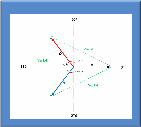
Understanding three phase voltage
Table of Contents
Table of Contents
Are you struggling to understand how to draw a phasor diagram for 3 phase? Are you having a hard time visualizing complex three-phase electrical systems? If so, you’re not alone. Understanding how to draw phasor diagrams for 3 phase can be daunting, but it’s a critical skill for anyone working in the electrical engineering field.
Anyone who has worked with three-phase electrical systems knows that it can be tricky to understand the voltage, current, and power relationships. This can lead to confusion and mistakes in design or maintenance, resulting in costly downtime and potential safety hazards.
So, how do you draw a phasor diagram for 3 phase? First, it’s essential to understand what phasors are and how they relate to three-phase electrical systems. Once you have a solid grasp of these concepts, you can start to draw phasor diagrams with confidence.
In summary, learning how to draw phasor diagrams for 3 phase is a critical skill for anyone working with electrical systems. It can be challenging, but with practice and patience, anyone can master the art of phasor diagramming.
How to Draw a Phasor Diagram for 3 Phase: Understanding the Basics
When I first started working with three-phase electrical systems, I found it challenging to understand voltage, current, and power relationships. However, once I learned about phasors, it became much easier to visualize these complex systems.
Phasors are rotating vectors that represent the magnitude and phase of an electrical quantity. They are used to represent AC signals mathematically and provide a way to visualize the relationships between voltage, current, and power in three-phase systems.
When drawing a phasor diagram for 3 phase, it’s crucial to understand the difference between line voltage and phase voltage, as well as line current and phase current. Line voltage and current refer to the total voltage and current in a system, while phase voltage and current refer to the voltage and current in a single phase.
 It’s also important to understand the difference between a star and delta connection in three-phase systems. In a star connection, each phase is connected to a common neutral point, while in a delta connection, each phase is connected to the next phase.
The Benefits of Drawing a Phasor Diagram for 3 Phase
One of the benefits of drawing a phasor diagram for 3 phase is that it allows you to visualize the relationships between voltage, current, and power in a three-phase system. This can help you diagnose problems, make adjustments, and optimize performance.
Additionally, phasor diagrams can help you understand the impact of changing voltage or frequency on a system, making it easier to optimize settings and improve efficiency.
Tips for Drawing Accurate Phasor Diagrams for 3 Phase
When drawing phasor diagrams for 3 phase, there are a few tips to keep in mind:
- Always label your phasors and vectors.
- Pay attention to the direction of rotation and the starting point.
- Make sure your phasors and vectors are drawn to scale.
- Use different colors to distinguish between different quantities (e.g., voltage, current, power).
Common Mistakes to Avoid When Drawing Phasor Diagrams for 3 Phase
There are also a few common mistakes to avoid when drawing phasor diagrams for 3 phase:
- Forgetting to label your phasors and vectors.
- Choosing the wrong starting point or direction of rotation.
- Not drawing your phasors and vectors to scale.
- Mixing up line and phase voltages or currents.
Conclusion of How to Draw a Phasor Diagram for 3 Phase
Drawing phasor diagrams for 3 phase can be a daunting task, but with practice and patience, anyone can master this critical skill. Phasors provide a way to visualize complex three-phase electrical systems and understand the relationships between voltage, current, and power. By following these tips and avoiding common mistakes, you can draw accurate phasor diagrams and optimize your system’s performance.
Question and Answer
Q: What is a phasor diagram?
A: A phasor diagram is a graphical representation of the magnitude and phase relationships between voltage, current, and power in a three-phase electrical system.
Q: Why are phasor diagrams important?
A: Phasor diagrams allow us to visualize complex three-phase electrical systems and understand the relationships between voltage, current, and power. This can help us diagnose problems, make adjustments, and optimize performance.
Q: What are some common mistakes to avoid when drawing phasor diagrams for 3 phase?
A: Common mistakes include forgetting to label phasors and vectors, choosing the wrong starting point or direction of rotation, not drawing to scale, and mixing up line and phase voltages or currents.
Q: Can I use phasor diagrams for single-phase electrical systems?
A: Yes, phasor diagrams can be used for single-phase systems as well. However, since there is only one phase, the diagram will be much simpler than in a three-phase system.
Gallery
Three Phase AC Star Circuit Phasor Diagram - YouTube

Photo Credit by: bing.com / phase phasor diagram star three ac circuit
How To Draw A Phasor Diagram - Free Wiring Diagram
Photo Credit by: bing.com /
Understanding Three Phase Voltage | Pacific Power Source

Photo Credit by: bing.com / phase three diagram phasor voltage understanding power source figure
Three Phase Delta Connection: Three Phase Power,Voltage,Current

Photo Credit by: bing.com / phase delta three connection power voltage current connected phasor diagram system load currents wire configuration voltages electric calculate know electrical
RLC Series Circuit - Electrical And Electronics Technology Degree

Photo Credit by: bing.com / phasor rlc impedance fasor rl lagging electrical sirkuit rangkaian vc circuits


